Click Box Maker
Click Box Maker
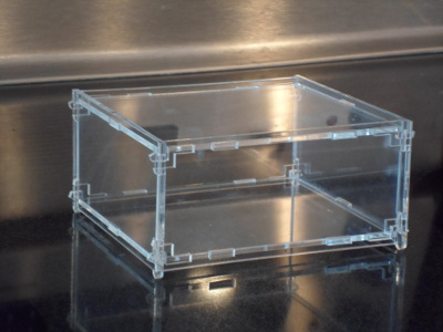
Most of you have seen, and some of you have made, a “click box” out of 1/8 Acryllic. These are used to house electronics, like the Arduino or Raspberry Pi. Here is the link.
http://www.thingiverse.com/thing:24461
I call this type of box a “click box” because it goes together without fasteners or glue, by using tabs and sockets with the last piece going together with a click from a flexible tab with tongue going into a socket, which is reversible for disassembly. This was just the type of box I wanted for other electronics projects, but in a different size. I looked around for some online program to make a click box automatically from user dimensions, but I couldn't find one. So I made one.
What I used was the program OpenSCAD to build a dxf file to import to LaserCut to run the LaserCutter.
OpenSCAD is a CAD program that doesn't get information by a user interactively drawing a picture with the mouse. It gets the information from code written in the SCAD language in the program interpreter. You write the code, save the code, edit the code, and when you push F6 the code makes a drawing in the viewing window of the interpreter. You can export this drawing to a dxf file, which we can import to LaserCut for cutting.
I wrote 3 programs, one for each unique side. Once you have downloaded and installed OpenSCAD, you simply copy the program into OpenSCAD, input your dimensions, and export a dxf file.
Terry W.
Instructions
1) Download OpenSCAD. Install it and make sure you set it for millimeters (mm).
2) Open a new file in OpenSCAD and Cut and Paste one of the part programs (Top, Side, Front) that are at the wiki page below.
3) Edit in the dimensions you want the box to be. Height, width, depth, and material thickness, all in mm. Because orthogonal surfaces sometimes have an inset due to the construction technique, all measurements are for the interior.
4) Compile and Render with F6 or menu DESIGN/COMPILE AND RENDER.
5) View from the Top by selecting from the menu VIEW/TOP.
6) Export to a dxf file by selecting from the menu DESIGN/EXPORT AS DXF.
7) Repeat for the other two surfaces, always making sure you type the same dimensions in each time.
8) Close OpenSCAD.
9) Move all files to the computer controlling the LaserCutter.
10) Open LaserCut.
11) Import File.
12) Select all lines with CTRL-A and select TOOLS/UNITE LINES and take the default.
13) Paint the tab holes with a different color and do those before cutting the exterior loop. Once the full part is cut with the exterior loop, the part can shift a bit. So always cut interior holes first to keep registration.
14) Save in ECP format.
15) Download to LaserCutter as normal.
16) Do all the normal things to bring up the LaserCutter and cut your piece.
Final Thoughts
There are obviously some limitations in the design. Tablength is 4 times the thickness, so if the box gets small in relation to the thickness the tab sockets can start to interfere or fatally weaken the box.
Also the interior of the clickslots aren't radiused and are a stress riser. But I have not had any failures at this point in the sizes I have built. In addition, the small tongues on the click arms may not be of optimal size.
And finally the pieces wiggle a slight amount when put together. This could be tightened up. The reason for it is when the laser cuts, it melts a chasm of non-zero width. This is equivalent to the woodworking term “kerf”. The kerf on our laser for 1/8 (3mm) plexiglass is about 5 mil, other materials and thicknesses will be different. 1 mil (one thousandths of an inch) is about .04 mm. So when we cut a tab, it will be 5 mil (2.5 mil off each side) less wide. And holes will be 5mils bigger in each direction. When we cut our tabs and tab sockets, I cut them at heights of 1*thickness and widths of 4*thickness. For 3mm Plexiglass, when we cut a 12mm x 3mm tab and a 12mm x 3mm socket, it is actually a 11.8mm x 3mm tab and a 12.2mm x 3.05mm hole. I have put a variable in the program to account for differences between the tab size and the hole size, because I initially thought I would need to cut the hole bigger than the tab. I didn't and thus set it to zero. We could use a negative value to tighten the hole/tab wiggle, but I would need to change the program slightly as we only need half as much tightening in the 3mm direction because that is the thickness of the piece for the tab which isn't changed by cutting. In that direction the hole gets bigger due to kerf and but the tab stays the same.
Good Luck.
Comments from Users
This space intended for comments/problems/suggestions from members who have used this project.
